
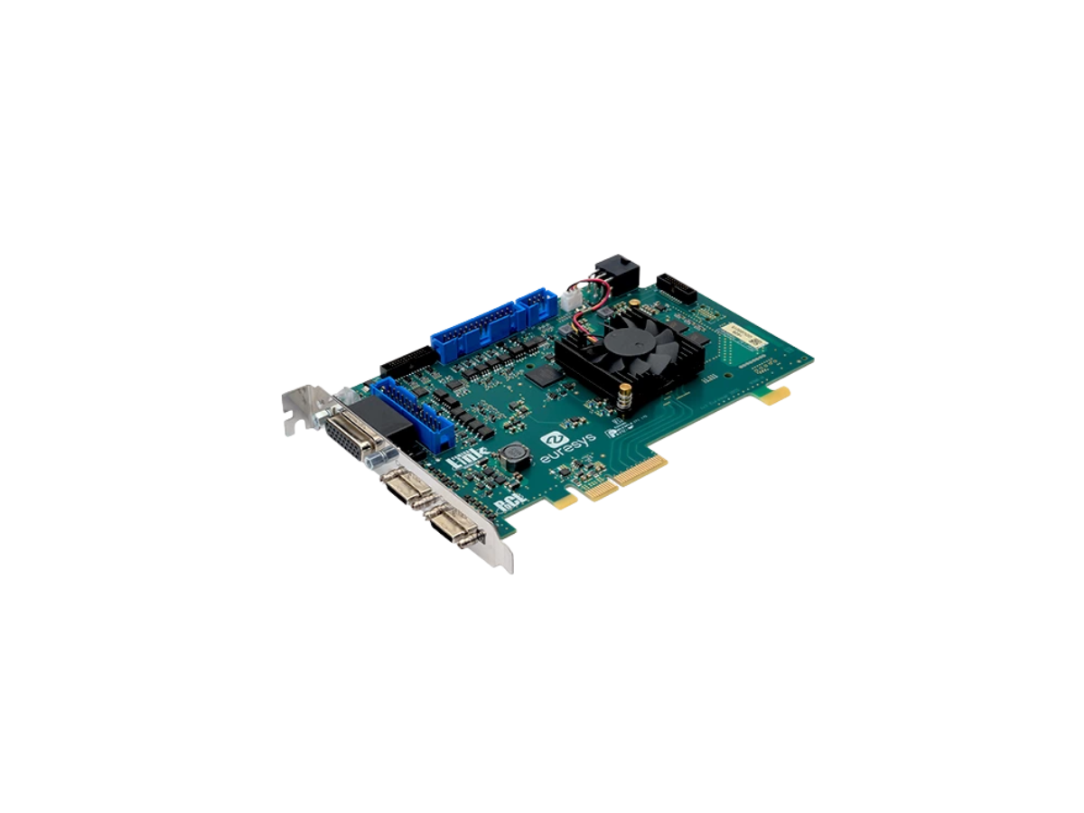
Grablink Duo Key Features:
- Supports two independent Base-configuration Camera Link cameras
- Synchronized or independent acquisition modes for flexible system design
- High-throughput DMA transfers to reduce host CPU load
- Digital I/O and encoder support for precise timing and hardware integration
- Comprehensive SDKs and drivers, including GenICam compatibility
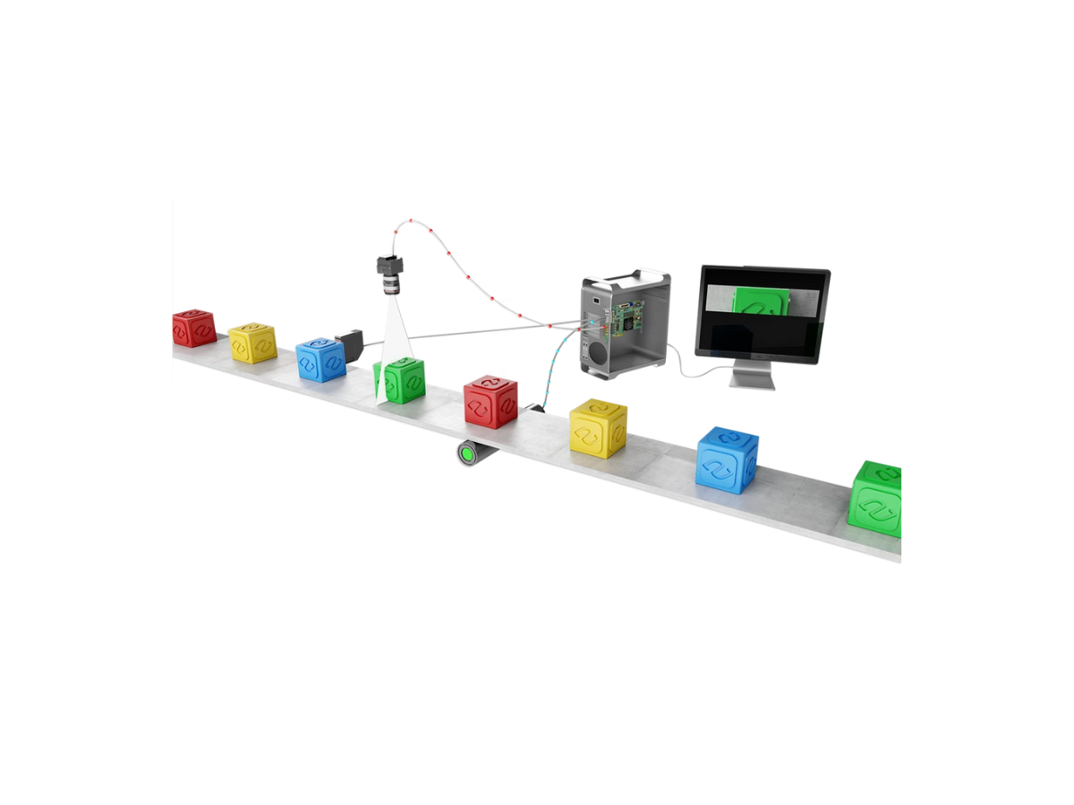
Ideal Solution For:
- Dual-camera inspection and multi-view imaging
- Stereo vision and depth measurement systems
- Electronics, PCB, and semiconductor inspection
- Packaging, printing, and surface-quality inspection
- Laboratory and scientific imaging requiring dual acquisition channels
Technical Specifications
Specification |
Grablink Duo |
Mechanical |
|
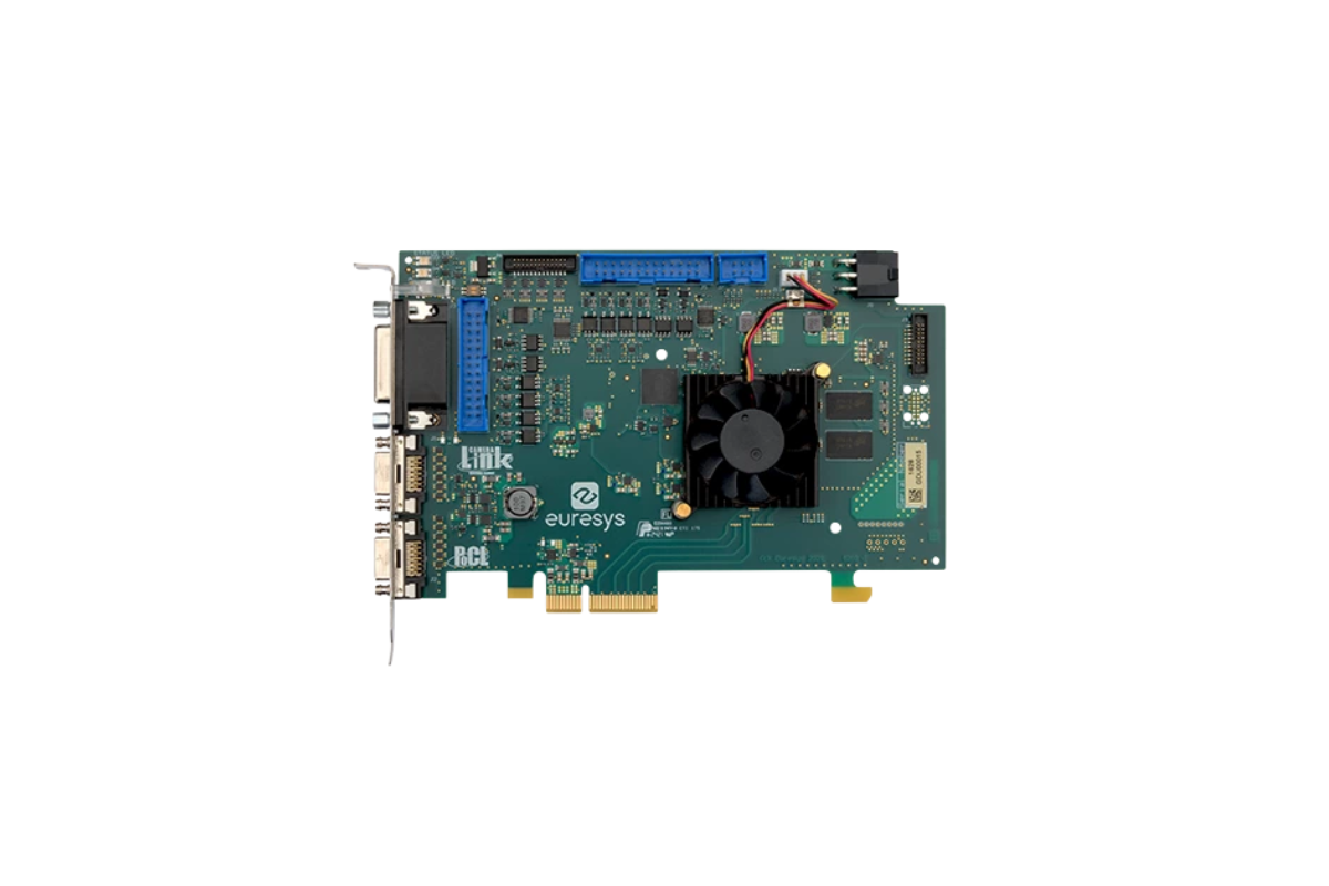
| Form Factor | PCI Express Card |
| Format | Standard, half length, 4-lane PCI Express Card |
| Cooling | Air-cooling, fan-cooled heatsink |
| Mounting | For insertion in a standard height, 4-lane or higher, PCI Express card slot |
| Connectors |
'A' on card bracket: 26-pos SDR socket with M2 jack socket screws, CL camera A input, PoCL output 'B' on card bracket: 26-pos SDR socket with M2 jack socket screws, CL camera B input or Camera A second cable input, PoCL output 'External I/O' on card bracket: 26-pin 3-row high-density D-Sub female socket with UNC4-40 jack socket screws, I/O lines and power output 'Internal I/O 1' on PCB: 26-pin 2-row 0.1" pitch pin header with shrouding, I/O lines and I/O power output 'Internal I/O 2' on PCB: 26-pin 2-row 0.1" pitch pin header with shrouding, I/O lines and I/O power output. 'I/O Extension' on PCB: 26-pin 2-row 0.05" pitch pin header with shrouding, I/O extension cable socket. 'C2C-Link' on PCB: 6-pin 2-row 0.1" pitch pin header with shrouding, card-to-card link 'Auxiliary Power Input' on PCB: 6-pin PEG power socket, 12V DC power input for PoCL and I/O power output. |
| LED Indicators | 'A', 'B' on bracket: Bi-colour red/green LEDs, Camera Link status indicator |
| Switches | 'Recovery' on PCB: 3-pin 1-row 0.1" header or 2-way DIP switch, firmware emergency recovery |
| Dimensions | PCB L x H: 167.65 mm x 111.15 mm [6.6 in x 4.38 in] |
| Weight | 167 g |
Host Bus |
|
| Standard | PCI Express 2.0 |
| Link Width | 4 lanes, 1 lane or 2 lanes with reduced performance |
| Link Speed | 5.0 GT/s (PCIe 2.0), 2.5 GT/s (PCIe 1.0) with reduced performance |
| Max Payload Size | 512 bytes |
| Peak Delivery Bandwidth | 2,000 MB/s |
| Effective (sustained) Delivery Bandwidth | 1,700 MB/s (Host PC motherboard dependent) |
| Power Consumption | Typ. 7.1 W ( 2.7 W @ +3.3V, 4.4 W @ +12V), excluding camera and I/O power output |
Camera/Video Inputs |
|
| Camera Interface Standard | Camera Link 2.0 |
| Max Link Speed | 85 MHz |
| Camera Power | PoCL |
| Connectors | Two Shrunk Delta Ribbon (SDR) Miniature Camera Link (MiniCL) |
| Number of Cameras |
One 80-bit / 72-bit / Full / Medium / Base configuration camera Or two Base configuration cameras |
| Max Number of Cameras | 2 |
| Line-scan Supported | Yes |
| Max Aggregated Camera Data Transfer Rate | 6.8 Gbps (850 MB/s) |
| CL Configuration | Base, Medium, Full, 72-bit, 80-bit |
| Camera Link Clock Frequency | From 20 MHz up to 85 MHz |
| PoCL |
PoCL Safe Power: Two independent controllers, PoCL Device detection and automatic power-on, Overload and short-circuit protection. A +12V power source must be connected to the AUXILIARY POWER INPUT connector using a 6-pin PEG cable |
| Camera Types | Area-Scan Cameras: Grayscale and colour (RGB and Bayer), Line-Scan Cameras: Grayscale and Colour (RGB) |
| Camera Pixel Formats Supported |
Mono8, Mono10, Mono12, Mono14, Mono16 BayerXX8, BayerXX10, BayerXX12, BayerXX16 where XX = GR, RG, GB, or BG RGB8 |
On-board Processing |
|
| On-Board Memory | 512 MB |
| Image Data Stream Processing | Unpacking of 10-/12-/14-bit to 16-bit with selectable justification to LSb or MSb |
| Input LUT |
Monochrome 8-bit to 8-bit transformation Monochrome 10-bit to 8-, 10- or 16-bit transformations Monochrome 12-bit to 8-, 12- or 16-bit transformations |
| Bayer CFA to RGB decoder | Advanced interpolation method using average and median functions on a 3x3 kernel |
| Data Stream Statistics | Measurement of frame rate (area-scan only), line rate, data rate. Configurable averaging interval. |
| Event Signaling and Counting |
The application software can be notified of the occurrence of various events: Standard event: the EVENT_NEW_BUFFER event notifies the application of newly filled buffers, A large set of custom events Custom events sources: I/O Toolbox events, Camera and Illumination control events. Each custom event is associated with a 32-bit counter that counts the number of occurrences The last three 32-bit context data words of the event context data can be configured with event-specific context data: Event-specific data, State of all System I/O lines sampled at the event occurrence time, Value of any event counter |
General Purpose Inputs/Outputs |
|
| Number of Lines |
20 I/O lines: 4 differential inputs (DIN) 4 singled-ended TTL inputs/outputs (TTLIO) 8 isolated inputs (IIN) 4 isolated outputs (IOUT) NOTE: The number of I/O lines can be extended using I/O modules attached to the I/O EXTENSION connector. |
| Usage |
Any I/O input lines can be used by any LIN tool of the I/O Toolbox Selected pairs of I/O input lines can be used by any QDC tool of the I/O toolbox to decode A/B signals of a motion encoder |
| Electrical Specifications |
DIN: High-speed differential inputs, up to 5 MHz, compatible with ANSI/EIA/TIA-422/485 differential line drivers and complementary TTL drivers TTLIO: High-speed 5V-compliant TTL inputs or LVTTL outputs, compatible with totem-pole LVTTL, TTL, 5V CMOS drivers or LVTTL, TTL, 3V CMOS receivers IIN: Isolated current-sense inputs with wide voltage input range up to 30V, signaling up to 200 kHz, individual galvanic isolation up to 250VDC and 170 VAC, compatible with totem-pole LVTTL, TTL, 5V CMOS drivers, RS-422 differential line drivers, potential free contacts, solid-state relays and opto-couplers IOUT: Isolated contact outputs compatible with 30V / 100mA loads NOTE: IIN and IOUT lines provide a functional isolation grade for the circuit technical protection. It does not provide an isolation that can protect a human being from electrical shock. |
| Filter Control | Glitch removal filter available on all System I/O input lines. Configurable filter delay: Custom value, Fixed values for DIN and TTLIO lines: 50 ns, 100 ns, 200 ns, 500 ns, 1 µs |
| Polarity Control | Yes |
| Power Output | Non-isolated, +12V, 1A with electronic fuse protection |
| I/O Toolbox Tools |
The I/O Toolbox is a configurable interconnection of tools that generates events (usually triggers): Line Input tool (LIN): edge detector delivering events on rising or falling edges of any selected input line. Quadrature Decoder tool (QDC): a composite tool including: A quadrature edge detector delivering events on selected transitions of selected pairs of input lines, an optional backward motion compensator for clean line-scan image acquisition when the motion is unstable, a 32-bit up/down counter for delivering a position value. User Actions Scheduler tool (UAS): to delegate the execution of 'User Actions' at a scheduled time or encoder position. Possible user actions include setting low/high/toggle any bit of the User Output Register or generation of any User Events. Delay tool (DEL): to delay up to 16 events from one or two I/O toolbox event sources, by a programmable time or number of motion encoder ticks (any QDC events). Divider tool (DIV): to generate an event every nth input events from any I/O toolbox event source. Multiplier/divider tool (MDV): to generate m events every d input events from any I/O toolbox event source. The 'Input Tools' (LIN, QDC and UAS) can be further processed by the 'Event Tools' (DEL, DIV and MDV) to generate any of the following "trigger" events: The "cycle trigger" of the Camera and Illumination controller, the "cycle sequence trigger" of the Camera and Illumination controller, the "start-of-scan trigger" of the Acquisition Controller (line-scan only), the "end-of-scan trigger" of the Acquisition Controller (line-scan only) |
| I/O Toolbox Composition |
Determined by the selected firmware variant: '1-camera': 8 LIN, 1 QDC, 1 UAS, 2 DEL, 1 DIV, 1 MDV, 2 C2C '2-camera': 8 LIN, 2 QDC, 1 UAS, 2 DEL, 2 DIV, 2 MDV, 2 C2C '1-camera, line-scan': 8 LIN, 1 QDC, 1 UAS, 2 DEL, 1 DIV, 1 MDV, 3 C2C '2-camera, line-scan': 8 LIN, 2 QDC, 1 UAS, 2 DEL, 2 DIV, 2 MDV, 3 C2C |
C2C-Link |
|
| Description |
Accurate synchronization of the trigger and the start-of-exposure of multiple grabber-controlled area-scan cameras. Accurate synchronization of the start-of-cycle, start-of-scan and end-of-scan of multiple grabber-controlled line-scan cameras. |
| Specification |
C2C-Link synchronizes cameras connected to: the same card, different cards in the same PC (requires an accessory cable such as the "3303 C2C-Link Ribbon Cable" or a custom-made C2C-Link cable), different cards in different PCs (requires one "1636 InterPC C2C-Link Adapter" for each PC and one RJ 45 CAT 5 STP straight LAN cable for each adapter but the last one) Maximum distance: 120 cm inside a PC, 1200 m cumulated adapter to adapter cable length Maximum trigger rate: 2.5 MHz for configurations using a single PC, or up to 10 PCs and 100 m total C2C-Link cable length, 200 kHz for configurations up to 32 PCs and 1200m total C2C-Link cable length Trigger propagation delay from master to slave devices: Less than 10 ns for cameras on the same card or on different cards in the same PC, Less than 265 ns for cameras on different cards in different PCs (3 PCs and 40m total C2C-Link cable length) |
Software |
|
| Driver | eGrabber |
| Host PC OS |
Microsoft Windows 11, 10 for x86-64 (64-bit) processor architecture Linux for x86-64 (64-bit) and AArch64 (64-bit) processor architectures macOS for x86-64 (64-bit) and AArch64 (64-bit) processor architectures |
| APIs |
EGrabber class, with C++ and .NET APIs: .NET assembly designed to be used with development environments compatible with .NET frameworks version 4.6 or higher GenICam GenTL producer libraries compatible with C/C++ compilers: 'x86_64' dynamic library designed to be used with ISO-compliant C/C++ compilers for the development of x86-64 (64-bit) applications, 'aarch64' dynamic library designed to be used with ISO-compliant C/C++ compilers for the development of AArch64 (64-bit) applications |
| Momento Supported | Yes |